Aeotec Heavy Duty Smart Switch Gen5
Homeowner Summary
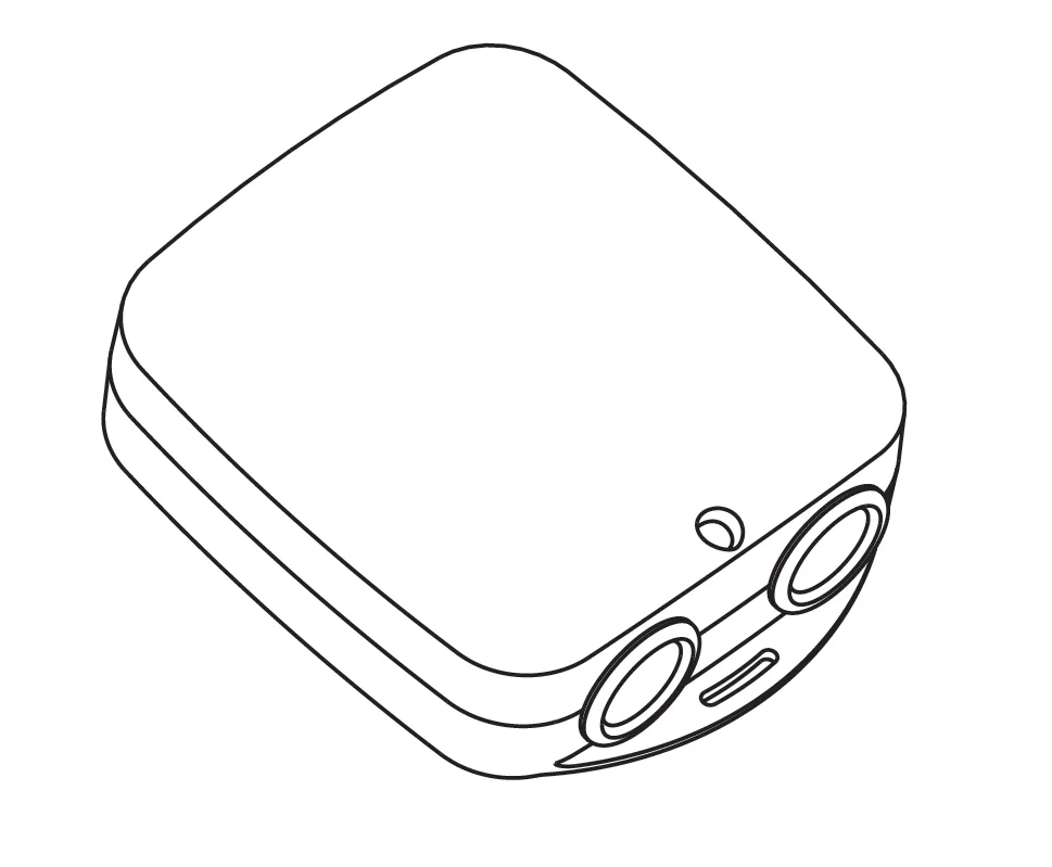
The Aeotec Heavy Duty Smart Switch Gen5 is a hardwired Z-Wave switch for high-power equipment — the kind of loads a plug-in smart switch can't handle, like water heaters, well pumps, and large motors. It switches the load on and off and reports power use back to Shipshape, so SAM can monitor heavy equipment the same way it monitors plugged-in appliances. It handles loads up to 40 amps.
Because it wires directly into your electrical system, a Heavy Duty Smart Switch must be installed by a licensed electrician. This is not a homeowner install. This guide explains what the device does and how it's wired so you understand the equipment in your home; the actual installation is a professional job.
⚠️ Electric shock hazard. Only qualified installation and maintenance personnel should wire or open this device. It must be installed behind an air-break switch / circuit breaker, with the circuit powered down and locked out during work.
How It Works
The Heavy Duty Smart Switch sits between your circuit breaker (the "AC Power" side) and the equipment it controls (the "Load" side). Inside are heavy-gauge terminals for both sides, a relay rated for high current, and a Z-Wave Plus radio (Aeotec Gen5). When Shipshape or you switch it, the relay opens or closes the circuit to the equipment; it also measures power draw and reports it over Z-Wave.
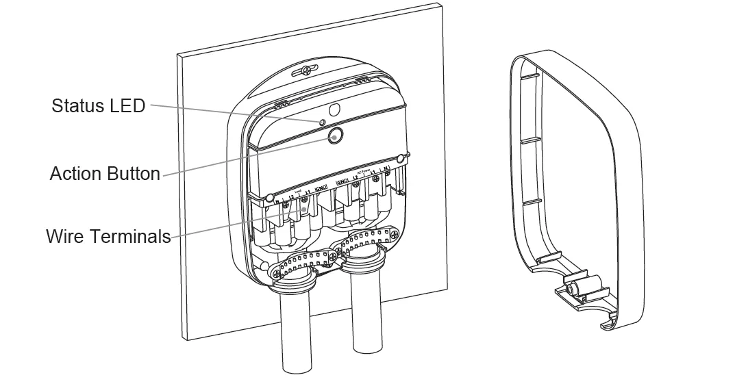
Key components:
- Action button — used for Z-Wave inclusion/exclusion and to turn the load on or off manually.
- Status LED — shows device status; blinks slowly and constantly while unpaired.
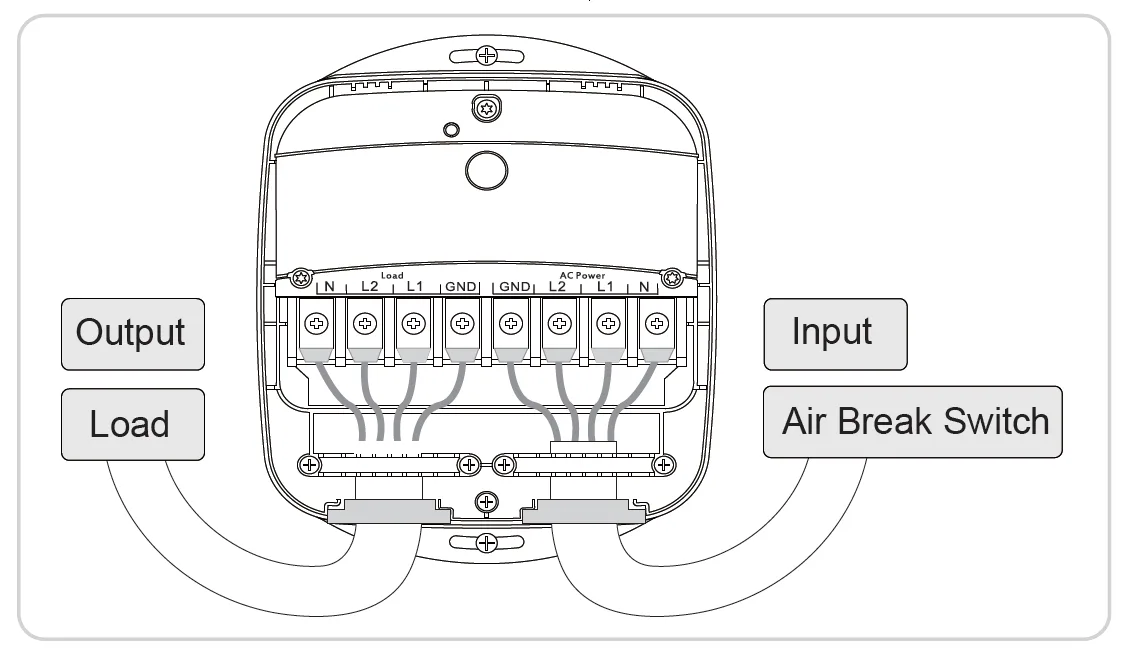
- Terminals — two groups: mains power connects to AC Power, the equipment connects to Load.
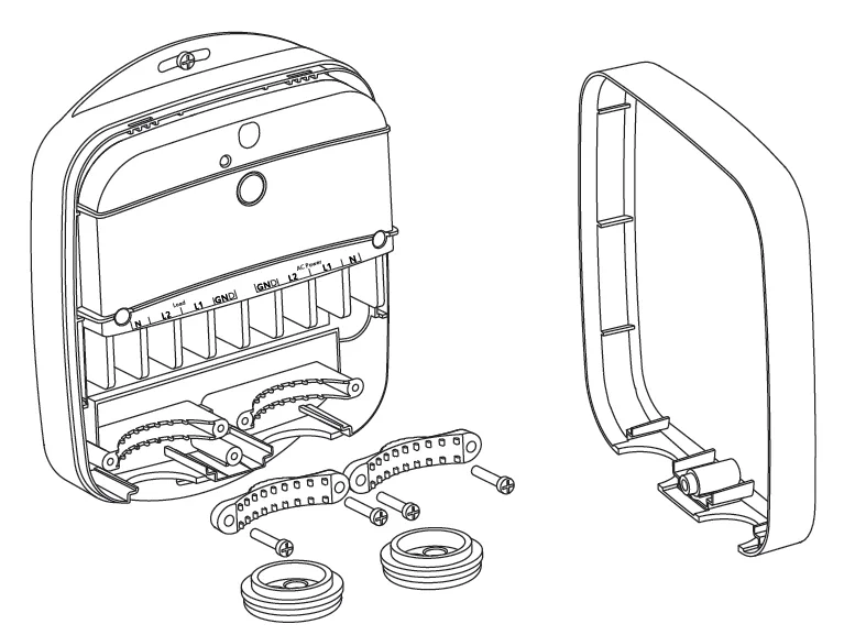
What's in the box: the switch, 8 AWG8 wire terminals, 8 AWG10 wire terminals, 2 mounting screws, and the instruction manual.
Wire sizing: use AWG10 wire for loads under 32 A, and AWG8 wire for loads above 32 A. Device current must not exceed 40 A.
Installation (Licensed Electrician Only)
The high-level wiring sequence — performed only by a qualified electrician with the circuit de-energized and locked out:
-
Switch off the air-break switch / breaker and confirm the circuit is dead. Lock and tag it off if it's out of sight.
-
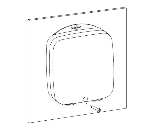
Mount the switch on a wall in a ventilated area with good heat dissipation. Drill a 2.5 mm hole for the top screw and a second hole 138 mm directly below it.
-
Loosen the lower screw to release the shell, and remove it to reach the terminals.
-
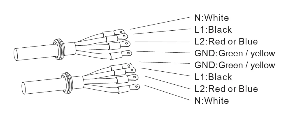
Strip the wires to length and crimp on the correct wire terminals (AWG8 or AWG10 by load). In the US, N is white, L1 is black, L2 is red or blue, and GND is green/yellow.
-
Connect the lines from the breaker to the AC Power terminals: live lines to L1 and L2, neutral to N, ground to GND. Wire the equipment to the Load terminals the same way. Tighten all terminals firmly.
-
Ensure the device has access to protective earth (green/yellow) and front-end short-circuit protection.
-
Power on and pair it with the gateway (below).
Aeotec publishes wiring diagrams for 120 V single-phase and 240 V two-phase circuits.
To factory reset the device, see Factory Resetting Aeotec Devices.
Pairing with Your Z-Wave Gateway
The switch must be paired before Shipshape can switch it or read its power use. While it's unpaired, its LED blinks.
- Turn off the equipment connected to the switch, so pairing can't damage it.
- Put your gateway into Z-Wave pairing (inclusion) mode.
- Press the Action button on the switch.
- If the LED stops blinking, the switch has joined your network. If it keeps blinking, pairing failed. Try again from step 2.
Maintenance Guide
- Don't open or service it yourself — only a licensed professional should work on a hardwired switch.
- Keep it ventilated. It must be installed where heat can dissipate, away from open flames, direct heat and direct sunlight.
- Stay within 40 A. The device must never carry more than its rated current.
- Keep children away. It contains small parts.
Pro Detail
Gateway compatibility
If you're adding the switch to a Z-Wave gateway yourself, check Aeotec's list of compatible gateways first. If your controller is an Aeotec Z-Stick or Minimote, follow Aeotec's own steps for that controller; for any other gateway, put the switch into inclusion mode with its Action button as that gateway's manual describes. Aeotec also publishes the switch's technical specifications.
EU wire colors
Under IEC 60446, the EU model has only neutral, L1 and ground (no L2 or L3): N is blue, L1 is brown, GND is yellow-green.
Shipshape Integration
The Heavy Duty Smart Switch lets Shipshape monitor high-power equipment — water heaters, pumps, and similar loads — that a plug-in switch can't handle. SAM watches the power signal for anomalies (a water heater drawing abnormal current, a pump that stops running) and can alert you, and an offline switch is flagged so the equipment it controls doesn't go unmonitored. For lighter, plug-in loads, see the Aeotec Smart Switch 6.